The Evolution of Accurate Length Control on Roll Form Cut-Offs
This article was written by Don Fanstone for Samco Machinery.
Don is a former president with Bailey Metal Products and Senior Manager with Samco Machinery Limited.
Rollforming has been a boon for the repetitive manufacture of linear metal shapes required in high volume applications. There is no comparison with items produced by press brakes with regards to consistency of shape or the required time to manufacture in man-hours.
Parts originally produced by press brakes did have one minimal advantage, that being the consistency of the length of each part. Sheets of a consistent length were sheared to the required part length and then formed on the press brake. While this was a minor plus, it was a factor when a customer required consistent lengths of roll formed products.
Rollformers produced a profile with consistency and permitted the production of parts of various lengths, especially long lengths as compared to that of press brakes.
Early rollformers required that the line to be stopped at the point that the sheet had to be cut to length. This could be by a chop saw, a stationary die, or by any means convenient. The stopping and starting of the line took away much of the potential gain in the reduction of man-hours and required the development of a means to cut parts “on the fly”, and eliminate the stopping and starting of the rollformer.
Producing a “Flying Shear” to cut light gage profiles without stopping the rollformer required that a number of items occur in sequence. Variance in the timing of any one of the requirements contributed to the variance obtained in the cut-length of succeeding parts.
The sequence was usually as follows:
- The end of the moving rollformed section contacted a stationary limit switch,
- The limit switch initiated a mechanical press cycle,
- A mechanical clutch was engaged to move the press through a complete 180 cycle,
- A limit switch actuator mounted on the clutch shaft contacted a second limit switch that activated an air cylinder to start advancing the die to line speed.
Co-incidentally, as the rollformed part was passing through the cut-off die, the ram of the press was moving downwards, and the die was moving forward, hopefully, reaching line speed at the moment of the cutting action.
Following the cutting action, the press returned to Top Dead Center and stopped, while the air cylinder was reversed to return the die to the “Home” position.
The variables in the sequence of cutting the sheet were numerous:
The cut-off signal was usually generated by the rollformed part striking of a limit switch that was mounted on a run-out table. Depending upon the rigidity of the run-out table, and the variance of striking the limit switch at the same point each time, all factors contributed to a potential variance in the length of the parts.
The press did not always stop at absolute Top Dead Center, causing a variance on the succeeding stroke as compared to the previous stroke.
Line air pressure used to advance the cut-off die forward was a major variable depending upon other equipment drawing supply from the plants compressed air system. If there was a large draw on the air system, it sometimes required adjustment of the limit switch on the clutch to move the air cylinder slightly sooner to get the die up to line speed. Ideally, a large air storage tank maintained at 100 PSI was the requirement to maintain consistency.
The lubrication of the slides under the cut-off die played a minor part in the consistency of the cut due to the rate of advance of the die.
The rate of the press in cycles per minute was a factor. Slow acting presses were notorious for inconsistent length control.
The distance the die traveled in the down stroke prior to making the cut was a factor, the longer the stroke, less accuracy. Time is accuracy!
Considering all of the factors involved, the striking of the limit switch consistently, variance in the line air pressure due to other shop equipment drawing upon the supply, the quality of the clutch and brake on the mechanical press, the distance the press ram was required to travel on the down stroke and the repetitive accuracy of the die advance cylinder in relation to the linear position of the formed section; all contributed to relatively inconsistent lengths in light gage roll formed products.
Most sections were run at approximately 120 to 150 FPM and were usually accurate within +/- 1/4″, but not consistently. Depending upon the operators ability to set the cut-off limit switch, if it was set at the high end of the tolerance, many of the agricultural siding sheets were essentially “too long” if they had to fit into a specific siding application with fixed top and bottom locations.
Running a rollform line at 150 FPM is moving at 1800 Inches Per Minute, and holding 1/2″ in 1800″ produced accuracy of 1/4 of 1%. Good, but not good enough.
Advances were made with roll formed sections having a rigid shape and being produced from 20-gage material (.036″). These parts were able to strike a preset arm (in lieu of a limit switch) that “pulled” the cutoff die with it. As the die traveled with the section, the press was activated and accurate lengths were cut repetitively. Pulling a large die was usually not feasible.
In the 1960’s, the air press was devised to move the die down at a high rate of speed with a relatively short travel distance of 3″ to cut the section.
Air presses create one-half of the rated tonnage by the inertia generated by the ram plate being forced down by the explosive introduction of air into an air bag or an air cylinder usually having a 3″ stroke. One-half of the rated tonnage is developed by the area of the cylinder expressed in square inches multiplied by the air pressure in pounds per square inch.
When setting an air press, it was usually a guesstimate to determine where the ram was to be positioned with respect to the distance the ram traveled before striking the die. If the ram were located too close to the die, the press would not develop sufficient inertia before it started to cut the section. Additionally, the ram had to overcome the pre-loaded pressure of the ram return springs as well as the increasing pressure of these springs as the ram travels the 3″ stroke prior to cutting the section. Due to the increasing pressure of the return springs as the ram descended, the press tonnage was being reduced throughout the length of the stroke.
Air presses are extremely fast acting compared to mechanical presses. This fast action reduced the time from when the rollformed sheet struck the length limit switch, and the actual cutting of the section.
Due to the “explosive action” of the air press, it was necessary to provide a means to stop the press from traveling too far and damaging the die. Down stops, made of a high-density type of plastic were incorporated as adjustable down-stops. These down stops transferred the unused energy of the press stroke into the base of the press, and over time, caused the floor under the press to deteriorate due to the transmitted shock.
At high rates of speed mechanical die accelerators supplanted air-actuated die-accelerators. The mechanical die accelerator was fixed to the top plate of the die, and incorporated an adjustable angular striker plate. The striker contacted corresponding rollers on the bottom die plate, converting vertical motion into linear motion to accelerate the die forward, allowing the die to approximately reach line speed prior to the actual cut occurring. Air cylinders and or springs were used to return the die to the home position.
Getting the right springs to return the die to the “Home” position also caused challenges at times. Too heavy a spring would return the die too fast and it would bounce off of the Home position stop blocks. This caused another variable if the operator or set-up person was not aware of what may be causing a length variation.
Air presses filled a need for cutting-off light gage roll formed sections at relatively high speeds and with a variance of +/- 1/8″, were twice as accurate as using mechanical presses. On the downside, they are noisy, and will, over time, cause the floor to deteriorate due to the transmitted shock to the base of the press.
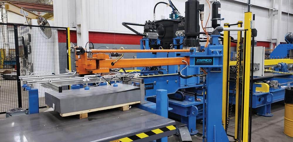
Samco Machinery Ltd, located in Toronto, Ontario, undertook the development of high speed hydraulics to actuate Cut-Off dies and In-Line Piercing applications in the mid 1990’s. Historically, hydraulics was relatively slow acting, and to use such an application required extensive engineering development and close co-operation with a major supplier. The development of high-speed valving helped to make this possible.
Essentially, a frame was developed to mount an in-house custom built hydraulic cylinder and two shear blades, one being fixed and one moving. The shear blades contain inserts that have the shape of the part to be severed, accurately wire-cut by an electrical discharge machine (EDM). The leading or entry shear blade is mounted in a fixed position, while the second shear blade moves as required, (up and down, or angularly) to produce a slug-less cut.
The sliding shear blade frame is attached to the hydraulic piston which controls the length of the stroke based upon the length of time that the hydraulic valve is open to advance the punch, and then reversed to return the punch to the upper or home position.
With the shear blade being wire-cut to the shape of the part, the time that the die travels to shear the part is literally instantaneous. This eliminates the time value of the mechanical press making a complete cycle of the ram, or the air press developing inertia on the down stroke.
Further developments in machine controllers with infinite adjustment of the time that valves are opened or closed made for highly accurate adjustments.
Adding to the hydraulic shear capabilities was the gaining popularity of “Closed Loop” circuitry. This type of cut-off has virtually supplanted “Open-Loop” style cut-off’s for accuracy in lengths at high speeds, and the relationship of pre-pierced holes to the end of the section.
A further refinement came with machine controllers that compensated for numerous factors in the complete press cut-off cycle.
A major advantage is that the tonnage developed by the hydraulic cylinder is constant throughout the length of the stroke; from the moment it starts the stroke, to the point at which it is reversed and returned to TDC.
Limit switches have long been replaced by Rotary Transducers that contact the material with an accurately sized wheel that drives a finely graduated optical reader as the material passes underneath. This produces an extremely accurate length measurement and corresponding signal to effect the cutting action. With an accurate repetitive signal, and the shortest length of a fast acting stroke possible, length accuracies of +/- 1/32″ are standard with a closed loop system operating at 300 FPM or greater.
Samco also uses the hydraulic application to pierce holes in many products, including light and heavy gage steel studs. Standard practice is to pierce holes in light gage steel studs at two feet on centre, (or as programmed), at speeds of 300 FPM (or higher with two pierce dies) or 150 holes a minute, or one hole every .40 seconds. Essentially, the punch is advanced to pierce a hole, then reversed to remove the punch, and then the die is returned to the starting position (home base) 150 times per minute.
Samco continues to improve the speed and repetitive accuracy of hydraulic piercing and cut-off technology by the application of the latest engineering technology. This technology, coupled with over 35 years of building rollformers and all of the related equipment needed to convert coil material into finished parts makes Samco an ideal source to solve your rollform manufacturing requirements.
Samco Can Provide:
- In-line welding of rollformed parts
- Programmed Punch-Anywhere systems across the width or length of the section.
- Complete part processing systems from coil to finished part,
- Complete shelving lines, automotive parts, garage doors, etc. etc.
- Auto-Setting of stud widths, leg heights, and material gage changes,
- Quick change rafted lines,
- Curved roll formed parts cut to length without stopping.